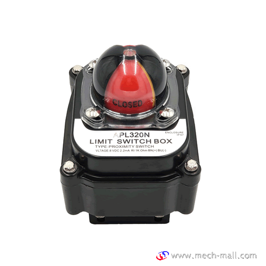
APL-320N Limit Switch Box
Introduction:
APL-320 Limit Switch Box , also can be called Valve Position Indicator or valve position monitor, is a kind of field instrument for detecting valve status in automatic control system.
Features:
- Enclosure : Weatherproof IP67/NEMA4&4X (Standard ) IP68(Option)
- Solid and beautiful design & various options available
•3~4 additional switches •8~16 points Terminal Strips - Bolts on visual position indicator
- Dual cable entries : 2 x 1/2 NPT(Standard ) M20, PG13.5, PF1/2”, PT1/2”.(Option)
- Terminal Strips : 8 points(0.08-2.5m)
- Captive cover bolts
- Easy mounting bracket
NAMUR standard stainless steel shaft and stainless steel or steel bracket.
Ordering Code:
Standard Specification:
| Model
Specification |
APL- 2N Series | APL- 3N Series | APL- 4N Series | APL- 5N Series |
| Enclosure | Weatherproof IP67/NEMA4&4X | Weatherproof IP67/NEMA4&4X | Weatherproof IP67/NEMA4&4X Explosionproof E EX d IIB T6 | Weatherproof IP67/NEMA4&4X Explosionproof E EX d IIC T6 |
| Cable entries | Two NPT1/2” | Two NPT1/2” | Two NPT3/4” | Two NPT3/4” |
| Ambient temperature | -20℃~ 80℃ | -20℃~ 80℃ | -20℃~ 80℃ | -20℃~ 80℃ |
| Terminal strips | 8 points (0.08-2.5m) | 8 points (0.08-2.5m) | 8 points (0.08-2.5m) | 8 points (0.08-2.5m) |
| Position indicator | 0 ~ 90。(90。turn free join) close:red open:yellow | 0 ~ 90。(90。turn free join) close:red open:yellow | 0 ~ 90。(90。turn free join) close:red open:yellow | 0 ~ 90。(90。turn free join) close:red open:yellow |
| Switches | Mechanical switch x2 proximity sensor x2 | Mechanical switch x2 proximity sensor x2 | Mechanical switch x2 proximity sensor x2 | Mechanical switch x2 proximity sensor x2 |
| Painting | Chromate Polyester podwer coating(black) | Chromate Polyester podwer coating(black) | Chromate Polyester podwer coating(black) | Chromate Polyester podwer coating(black) |
Option Specification:
| Specification Model | APL- 2N Series | APL- 3N Series | APL- 4N Series | APL- 5N Series |
| Enclosure | Weatherproof IP68 | Weatherproof IP68 | Weatherproof IP68 | Weatherproof IP68 Explosionproof E EX d IIB T6
E EX ia IIC T6 |
| Cable entries | Two PF1/2”, PT1/2” M20, PG13.5 | Two PF1/2”, PT1/2” M20, PG13.5 | FOUR PF3/4”, PT3/4” M20, M25 | Two NPT3/4”PT3/4” |
| Option temperature | – | -40℃ ~ 80℃
-20℃ ~ 150℃ |
– | – |
| Terminal strips | – | 16 points (0.08-2.5m) | 20 points (0.08-2.5mm) | – |
| Position indicator | three position close:red open:Green | three position close:red open:Green | three position close:red open:Green | three position close:red open:Green |
| Switches | – | Mechanical switch x4 proximity sensor x4 | Mechanical switch x4 proximity sensor x4 | Mechanical switch x4 proximity sensor x4 |
| Potentiometer | – | 1k ohm standard. 5k ohm. 0-10k ohm | 1k ohm standard. 5k ohm. 0-10k ohm | 1k ohm standard. 5k ohm. 0-10k ohm |
| Current output signal unit | – | 4~20mA DC
12.5 to 37VDC (24V typical) |
4~20mA DC
12.5 to 37VDC (24V typical) |
4~20mA DC
12.5 to 37VDC (24V typical) |
| Painting | Nylon others on request red, green, blue, yellow, silver | Nylon others on request red, green, blue, yellow, silver | Nylon others on request red, green, blue, yellow, silver | Nylon others on request red, green, blue, yellow, silver |
Wiring diagram:
Dimensions:
Installation requirements: The power must be turned off before opening the cover. After the product is installed, the technician needs to adjust it, let the valve go back and forth several times to determine that the limit switch signal is reliable.

