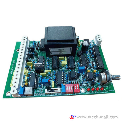
GAMX-2004 Control Board
Main technical parameters
- Input signal: 4-20mA
- input resistance: 250 Ω
- Output signal: 4-20mA, input signal and output signal are isolated, and the user does not need the isolate module
- Output resistance: 0-500Ω(special requirement: 0-750Ω)
- Feedback potentiometer: 0-1KΩ
- Basic error: ± 1%
- Dead zone: 0-3% adjustable
- Power supply voltage: 220V ± 10%
- Ambient temperature: -25 ℃ – + 55 ℃
- Relative humidity: ≤90% (no condensation)
Main functions
- Operation mode: forward direction: 4mA valve is closed, 20mA valve is opened. In reverse direction: 4mA valve is open and 20mA valve is closed.
- Interrupt hold: when the signal is lost, the actuator can remain in its original position, closed or open. And the actuator is set to remain in its original position by the interrupt signal at the factory.
- Manual operation: manual operation is to make the positioner simulate a 4-20mA input signal, and make the actuator manually adjust fully on or off.
- 0% position: positioner 0% makes the actuator fully closed.
- When terminals 19 and 34 are short circuited, automatic control is turned off and switch to manual operation. When terminals 34 and 35 are short circuited, the operation is in manual closing direction, while terminals 34 and 36 are in manual open operation. Remote control takes precedence over automatic control. When the controller is in the remote control position, the automatic control is blocked and does not work. Remote control is in jog state.
- Actuator operation direction:
In standard form: actuator (facing output shaft) is turned on clockwise
The control (changing the direction of motor rotation) can be changed by the dial switch to turn the actuator to open counter clockwise, and the direction of limit switch and torque switch can be changed at the same time.
7. Electric brake configuration: GAMX-2005 module: universal for 220VAC and 380VAC
Single phase power supply (220VAC) equipped with electric braking
The three-phase power supply (380VAC) makes the electric braking function ineffective by the dial switch, and the electric braking of the actuator is completed by the external circuit.
8. LED indication:
LED1 (red) power indicates; LED2 (green) actuator on; LED3 (red) actuator off;
LED4 (red) loses 4-20mA signal; LED5 (red) over torque switch.

