


Current Transformer LMK (BH)-0.66
- Introduction
- LMK-0.66,LMK3-0.66 series current transformers are indoor devices. It is used for current and energy measurement and insulation protection in AC lines with a rated frequency of 50 Hz and a rated voltage of 0.66 kV or less.
- Product standard: GB/T 20840.1&2
- Applicable Environmental Conditions
- The installation altitude does not exceed 1000m;
- The temperature of the surrounding medium is -5~+40℃
- The relative humidity of the air is not more than 80%;
- There is no dirty, corrosive and explosive medium that seriously affects the insulation of the transformer at the installation site.
- Technical Parameters
| Accuracy Class | Rated Voltage | Rated Frequency | Rated Primary Current | Rated Secondary Current | Rated Load | Withstand Voltage |
| Class 0.5, Class 0.2, Class 0.5S, Class 0.2S | 660V | 50Hz | 5-3000A | 5A, 1A | See it in in Chart below | 3kV/ 1min |
LMK (BH)-0.66 Rated Load
| Model | Rated Current Primary/ Secondary | Busbar | Number of Turn-throughs | Rated Load | Accuracy Class | |
| Sectional Dimension (mm2) | Number | |||||
| LMK-0.66 Ф20 | 75/5 | 20X10 | 1 | 1 | 3.75 | 0.5 |
| 100/5 | 20X10 | 1 | 1 | 5-3.75 | 0.5 | |
| 150/5 | 20X10 | 1 | 1 | 5-3.75 | 0.2 | |
| LMK-0.66 Ф30 | 30/5 | – | – | 5 | 5-3.75 | 0.5, 0.2 |
| 50/5 | – | – | 3 | 5-3.75 | 0.5, 0.2 | |
| 75/5 | – | – | 2 | 5-3.75 | 0.5, 0.2 | |
| 100/5 | – | – | 2 | 5-3.75 | 0.5, 0.2 | |
| 150/5 | 30X10 | 1 | 1 | 5-3.75 | 0.5 | |
| 200/5 | 30X10 | 1 | 1 | 5-3.75 | 0.5, 0.2 | |
| 250/5 | 30X10 | 1 | 1 | 5-3.75 | 0.5, 0.2 | |
| 300/5 | 30X10 | 1 | 1 | 5-3.75 | 0.5, 0.2 | |
| LMK-0.66 Ф40 | 150/5 | 40X10 | 1 | 1 | 5-3.75 | 0.5 |
| 200/5 | 40X10 | 1 | 1 | 5-3.75 | 0.5 | |
| 250/5 | 40X10 | 1 | 1 | 5-3.75 | 0.5 | |
| 300/5 | 40X10 | 1 | 1 | 5-3.75 | 0.5 | |
| 400/5 | 40X10 | 1 | 1 | 5-3.75 | 0.5, 0.2 | |
| 500/5 | 40X10 | 1 | 1 | 5-3.75 | 0.5, 0.2 | |
| 600/5 | 40X10 | 1 | 1 | 10-3.75 | 0.5, 0.2 | |
| LMK-0.66 Ф50 | 300/5 | 50X10 | 1 | 1 | 5-3.75 | 0.5 |
| 400/5 | 50X10 | 1 | 1 | 5-3.75 | 0.5 | |
| 500/5 | 50X10 | 1 | 1 | 5-3.75 | 0.5, 0.2 | |
| 600/5 | 50X10 | 1 | 1 | 10-3.75 | 0.5, 0.2 | |
| 750/5 | 50X10 | 1 | 1 | 10-3.75 | 0.5, 0.2 | |
| 800/5 | 50X10 | 1 | 1 | 10-3.75 | 0.5, 0.2 | |
| 1000/5 | 50X10 | 1 | 1 | 10-3.75 | 0.5, 0.2 | |
| LMK-0.66 Ф60 | 300/5 | 60X20 | 1 | 1 | 5-3.75 | 0.5 |
| 400/5 | 60X20 | 1 | 1 | 5-3.75 | 0.5 | |
| 500/5 | 60X20 | 1 | 1 | 5-3.75 | 0.5 | |
| 600/5 | 60X20 | 1 | 1 | 10-3.75 | 0.5, 0.2 | |
| 750/5 | 60X20 | 1 | 1 | 10-3.75 | 0.5, 0.2 | |
| 800/5 | 60X20 | 1 | 1 | 10-3.75 | 0.5, 0.2 | |
| 1000/5 | 60X20 | 1 | 1 | 10-3.75 | 0.5, 0.2 | |
| 1200/5 | 60X20 | 1 | 1 | 10-3.75 | 0.5, 0.2 | |
| 1500/5 | 60X20 | 1 | 1 | 15-3.75 | 0.5, 0.2 | |
| 2000/5 | 60X20 | 1 | 1 | 15-3.75 | 0.5, 0.2 | |
| LMK-0.66 Ф80 | 500/5 | 80X10 60X30 | 1-2 | 1 | 5-3.75 | 0.5 |
| 600/5 | 80X10 60X30 | 1-2 | 1 | 10-3.75 | 0.5 | |
| 750/5 | 80X10 60X30 | 1-2 | 1 | 10-3.75 | 0.5 | |
| 800/5 | 80X10 60X30 | 1-2 | 1 | 10-3.75 | 0.5, 0.2 | |
| 1000/5 | 80X10 60X30 | 1-2 | 1 | 10-3.75 | 0.5, 0.2 | |
| 1200/5 | 80X10 60X30 | 1-2 | 1 | 10-3.75 | 0.5, 0.2 | |
| 1500/5 | 80X10 60X30 | 1-2 | 1 | 15-3.75 | 0.5, 0.2 | |
| 2000/5 | 80X10 60X30 | 1-2 | 1 | 15-3.75 | 0.5, 0.2 | |
| LMK-0.66 Ф100 | 750/5 | 100X10 80X30 | 1-2 | 1 | 10-3.75 | 0.5 |
| 800/5 | 100X10 80X30 | 1-2 | 1 | 10-3.75 | 0.5 | |
| 1000/5 | 100X10 80X30 | 1-2 | 1 | 10-3.75 | 0.5, 0.2 | |
| 1200/5 | 100X10 80X30 | 1-2 | 1 | 10-3.75 | 0.5, 0.2 | |
| 1500/5 | 100X10 80X30 | 1-2 | 1 | 15-3.75 | 0.5, 0.2 | |
| 2000/5 | 100X10 80X30 | 1-2 | 1 | 15-3.75 | 0.5, 0.2 | |
| 2500/5 | 100X10 80X30 | 1-2 | 1 | 15-3.75 | 0.5, 0.2 | |
| 3000/5 | 100X10 80X30 | 1-2 | 1 | 20-3.75 | 0.5, 0.2 | |
| LMK-0.66 Ф120 | 1500/5 | 120X10 80X30 | 1-2 | 1 | 15-3.75 | 0.5, 0.2 |
| 2000/5 | 120X10 80X30 | 1-2 | 1 | 15-3.75 | 0.5, 0.2 | |
| 2500/5 | 120X10 80X30 | 1-2 | 1 | 15-3.75 | 0.5, 0.2 | |
| 3000/5 | 120X10 80X30 | 1-2 | 1 | 20-3.75 | 0.5, 0.2 | |
| 4000/5 | 120X10 80X30 | 1-2 | 1 | 20-3.75 | 0.5, 0.2 | |
| 5000/5 | 120X10 80X30 | 1-2 | 1 | 20-3.75 | 0.5, 0.2 | |
- Key Parts and Structure
The transformer shell is made of PC alloy material, the iron core is made of ordinary silicon steel sheet or ultra-microcrystalline material, and the secondary winding is wound with 100% pure copper wire.
- Installation, Using and Maintenance
- Transformers can be installed vertically or horizontally;
- The copper cross-section of the connecting wire connected to the secondary instrument and the relay is not less than 2.5mm’, the secondary terminals are marked as S1, S2, when the current flows from PI to P2, the secondary current flows from S1 to S2 through the external circuit , The transformer is depolarized;
- When the primary unit is connected with current, the secondary winding is strictly forbidden to open circuit to prevent high voltage;
- The storage place of the transformer should be dry and ventilated, and the long-term storage should be packed in a carton or wooden box;
- If the transformer storage period is more than one year, the insulation resistance and power frequency withstand voltage test should be carried out. If there is any change, it should be dried:
- Transformers shall be periodically verified to repair or replace products that fail verification.
- For bus-type transformers, when the user uses the product as a transformer with a small transformation ratio, the user can make multiple passes through the window according to the specified data on the product nameplate to meet the user requirements. For more details, pleas see Table 1.
Table 1 Current ratio and the number of turn-throughs
| 150 Ampere-turns | Current ratio(A) | 150/5 | 75/5 | 50/5 | 30/5 | 15/5 |
| Number of turn-throughs | 1 | 2 | 3 | 5 | 10 | |
| 200 Ampere-turns | Current ratio(A) | 200/5 | 100/5 | 50/5 | 40/5 | 20/5 |
| Number of turn-throughs | 1 | 2 | 4 | 5 | 10 |
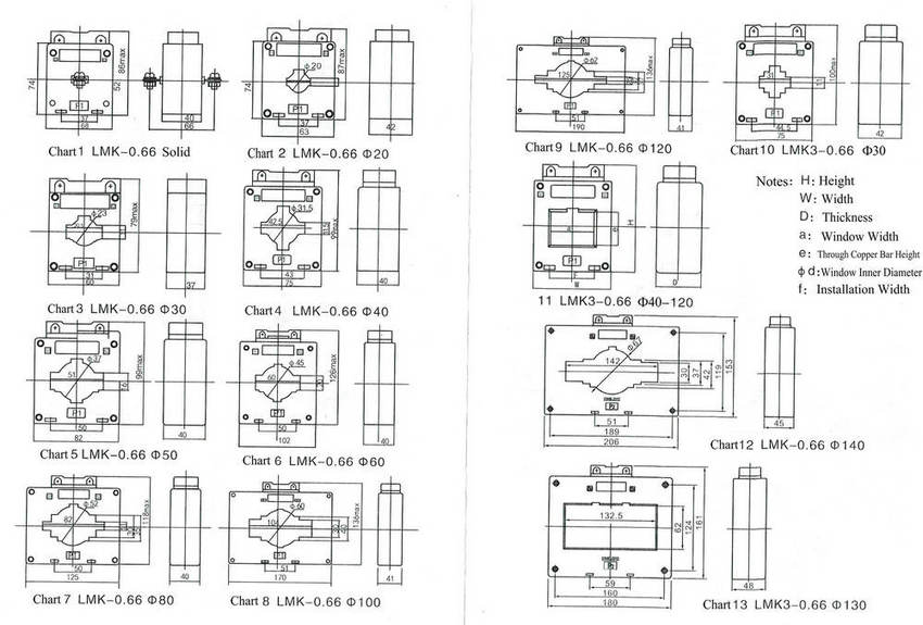
- Appearance and Installation Dimensions
Table 2 Installation Dimensions of Transformers (mm)
| Model | H | W | D | a | e | Фd | f | Notes |
| LMK-0.66 | ||||||||
| Solid | 87 | 68 | 40 | Chart 1 | ||||
| Ф20 | 87 | 68 | 42 | 23 | 7 | 20 | 37 | Chart 2 |
| Ф30 | 79 | 60 | 37 | 30.5 | 11 | 23 | 31 | Chart 3:0.5 Class |
| 100 | 75 | 42 | 31 | 11 | 23 | 44.5 | 0.2, 0.5S, 0.2S Class | |
| Ф40 | 99 | 75 | 40 | 42.5 | 11 | 31.5 | 43 | Chart 4 |
| Ф50 | 99 | 82 | 40 | 51 | 16 | 37 | 50 | Chart 5 |
| Ф60 | 126 | 102 | 40 | 60 | 20 | 45 | 50 | Chart 6 |
| Ф80 | 118 | 125 | 40 | 82 | 11 | 52 | 50 | Chart 7 |
| Ф100 | 136 | 170 | 41 | 104 | 30 | 60 | 51 | Chart 8 |
| Ф120 | 136 | 190 | 41 | 125 | 25 | 62 | 51 | Chart 9 |
| Ф140 | 153 | 206 | 45 | 142 | 30 | 67 | 51 | Chart 12 |
| LMK3-0.66 | ||||||||
| Ф30 | 100 | 75 | 42 | 31 | 11 | 44.5 | Chart 10 | |
| Ф40 | 100 | 75 | 45 | 42 | 31 | 44 | Chart 11 | |
| Ф50 | 106 | 87 | 45 | 52 | 31 | 54 | ||
| Ф60 | 112 | 99 | 45 | 62 | 31.5 | 54 | ||
| Ф80 | 120 | 118 | 45 | 83 | 32 | 60 | ||
| Ф100 | 124 | 140 | 49 | 102 | 32 | 50 | ||
| Ф120 | 154 | 165 | 49 | 122 | 52 | 54 | ||
| Ф130 | 161 | 180 | 48 | 132 | 62 | 59 | Chart 13 | |
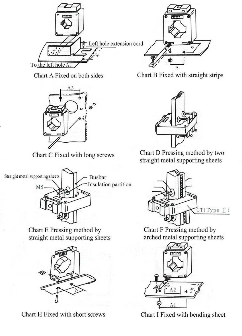
- Installation Methods