
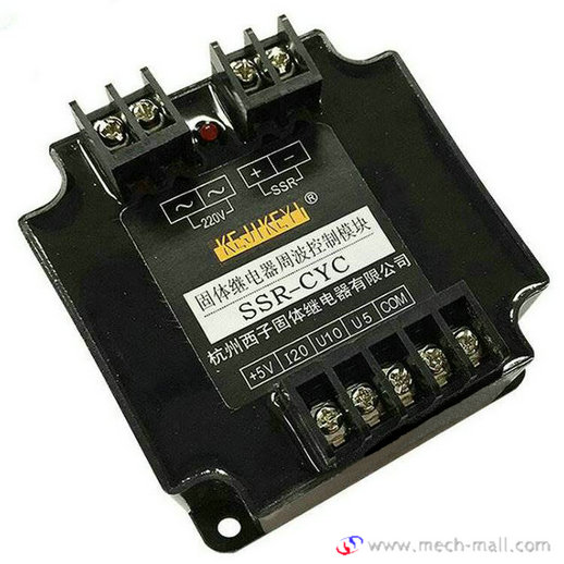
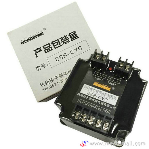
Cycle Control Module SSR-CYC
Introduction
Solid state relay cycle control module SSR-CYC works with zero-crossing single phase or three-phase solid state relay to accept 0-5V, 0-10V or 4-20mA temperature control instrument signal input, or the potentiometer is directly manually controlled to generate the corresponding cycle zero-crossing (CYC) control signal output, which directly drives the zero-crossing SSR and stably adjusts the total power output of the electric heating load. Since the current on the load is in the unit of complete sine wave and uniformly distributed, the regulation accuracy is improved, the higher harmonics caused by chopping (phase shifting) voltage regulation mode are avoided, and the power saving effect is obvious while reducing the pollution to the power grid.
Main performance indicators
| U5 | U10 | I20 | |
| Input impedance | 10KΩ | 20KΩ | 300Ω |
| Adjust dead band (0 output) | <=0.5V | <=1V | <=1mA |
| Regulation dead band (full load) | <=0.5V | <=1V | <=1mA |
| power waste | <=5W | ||
| Manual potentiometer | 2KΩ-10 KΩ | ||
| Control output maximum current | 40mA | ||
Dimensions

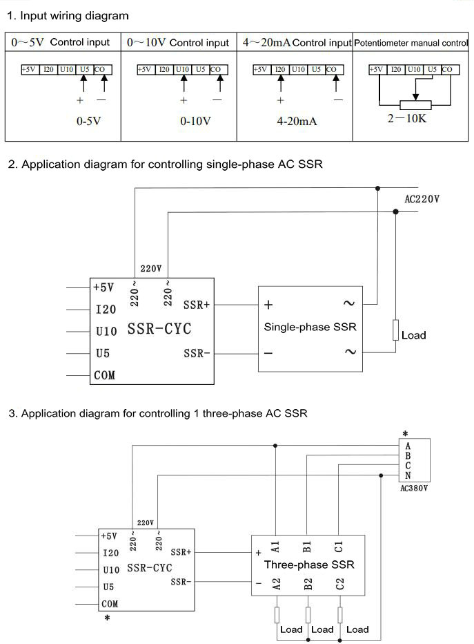
Wiring
The functional purposes of each terminal block are as follows:
| 220~ | AC 220V input |
| 220~ | |
| SSR+ | Cycle control output (connected to positive pole of SSR control input terminal) |
| SSR- | Cycle control output (connected to negative pole of SSR control input terminal) |
| +5V | Use when the potentiometer is manually controlled (refer to the wiring diagram) |
| I20 | 4~20mA control input signal positive pole |
| U10 | 0~10V control input signal positive pole |
| U5 | 0~5V control input signal positive pole |
| COM | Common negative pole of control input signal |
| Light-emitting tube | Turn on when the cycle control outputs high potential and turn off when it outputs zero potential |
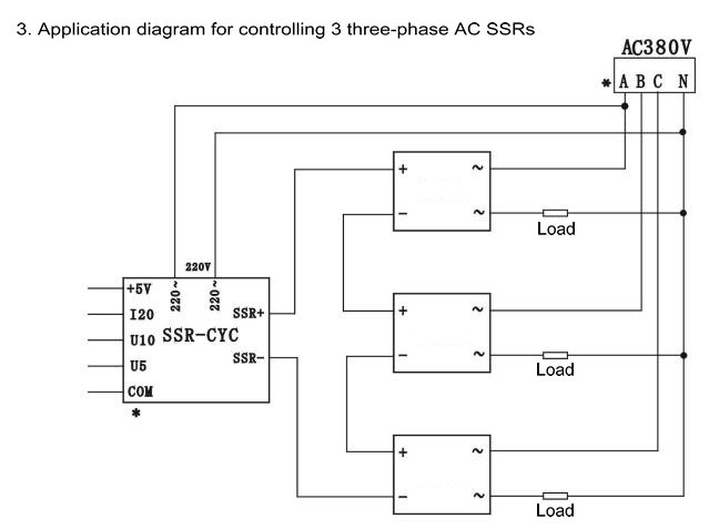
Application wiring diagram