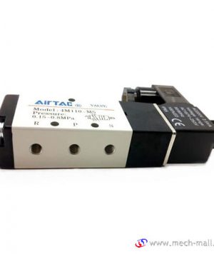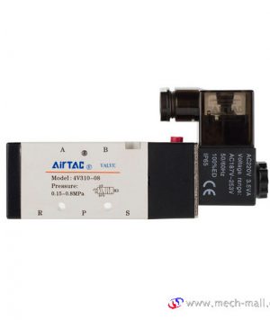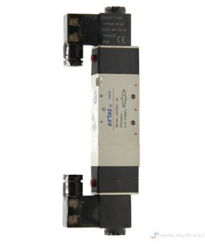

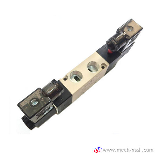
AirTAC Solenoid Valve 4V230C-06
Ordering Code:

Specification:
| Model | 4V210-06 | 4V220-06 | 4V230C-06 | 4V230E-06 | 4V230P-06 | 4V210-08 | 4V220-08 | 4V230C-08 | 4V230E-08 | 4V230P-08 |
| 4A210-06 | 4A220-06 | 4A230C-06 | 4A230E-M06 | 4A230P-06 | 4A210-08 | 4A220-08 | 4A230C-08 | 4A230E-08 | 4A230P-08 | |
| Position Number | Two-position Five-way | Three-position Five-way | Two-position Five-way | Three-position Five-way | ||||||
| Effective Sectional Area | 14mm2(CV=0.78) | 12mm2 (CV=0.67) | 16mm2 (CV=0.89) | 12mm2 (CV=0.67) | ||||||
| Joint Pipe Bore | Air Inlet=Outlet=Exhaust= G1/8″ | Air Inlet=Outlet=G1/4″ Exhaust=G1/8″ | ||||||||
| Working Medium | 40 Micron Filtered Air | |||||||||
| Motion Pattern | Inner Guide Type | |||||||||
| Working-pressure | 0.15~0.8MPa | |||||||||
| Max.Pressure Resistance | 1.2MPa | |||||||||
| Operating Temperature | 5~50°C | |||||||||
| Voltage Range | ±10% | |||||||||
| Power Consumption | AC:4.5VA DC:3W | |||||||||
| Insulation&Protection Class | IP65 / F Class.IP65 | |||||||||
| Wiring Form | Lead Wire or Connector type | |||||||||
| Highest Action Frequency | 5 Cycle/Sec | |||||||||
| Shortest Excitation Time | 0.05 Second | |||||||||
Function Introduction
1. Pilot-oriented mode:Internal pilot or external pilot.
2. Structure in sliding column mode: good tightness and sensitive reaction.
3. Three position solenoid valves have three kinds of central function for your choice.
4. Double control solenoid valves have memory function.
5. Internal hole adopts special processing technology which has little attrition friction, low start pressure and long service life.
6. No need to add oil for lubrication.
7. It is available to form integrated valve group with the base to save installation space.
8. Affiliated manual devices are equipped to facilitate installation and debugging.
9. Several standard voltage grades are optional.
Installation Instructions
1. Before installing, be sure the valve hasn’t been damaged via transportation.
2. It’s suggested to use the medium lubricated by 40μm filter element. Be aware of the flow direction and port size.
3. Please notice whether the installation condition accords with technical requirements (such as “voltage”, “actuation frequency”, “working pressure” and “scope of application temperature”), then the equipment can be installed and used.
4. Notice the flow direction of air during installation, P is the air intake, A (B) is the work port and R (S) is the exhaust outlet.
5. Take measure to avoid vibration and frozen.
6. Before using the fittings and tubes make sure they are clean. When connecting to fittings, be sure the PTFE Thread Seal Tape is used correctly.
7. To keep the dust away, please use the silencer for the exhaust ports. Never forget to install dirt-proof boot in air intake and outlet during dismounting.
8. After installing, please use the manual override to test valve first.