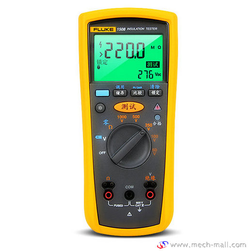
Fluke 1508 Insulation Tester
Introduction:
The Fluke model 1508 is a battery-powered insulation tester (hereafter, \”the Tester\”). This Tester meet CAT IV IEC 61010 standards. The IEC 61010 standard defines four measurement categories (CAT I to IV) based on the magnitude of danger from transient impulses. CAT IV Testers are designed to protect against transients from the primary supply level (overhead or underground utility
service).
The Tester measures or tests the following:
- AC / DC Voltage
- Earth-Bond Resistance
- Insulation Resistance
Resistance
| Maximum Voltage Applied to any Terminal | 600 V ac rms or dc |
| Storage Temperature | -40 °C to 60 °C |
| Operating Temperature | -20 °C to 55 °C |
| Temperature Coefficient | 0.05 x (specified accuracy) per °C for temperatures <18 °C or >28 °C |
| Relative Humidity | Noncondensing
0 % to 95 % @ 10 °C to 30 °C 0 % to 75 % @ 30 °C to 40 °C 0 % to 40 % @ 40 °C to 55 °C |
| Vibration | Random, 2 g, 5-500 Hz per MIL-PRF-28800F, Class 2 instrument |
| Shock | 1 meter drop per IEC 61010-1 2
nd Edition (1 meter drop test, six sides, oak floor) |
| Electromagnetic Compatibility | In an RF field of 3 V/M, accuracy = specified accuracy (EN 61326-1:1997). |
| Safety | Complies with ANSI/ISA 82.02.01 (61010-1) 2004, CAN/CSA-C22.2 NO. 61010-1-04, and
IEC/EN 61010-1 2 nd Edition for measurement category IV 600 V (CAT IV) |
| Certifications | CSA per standard CSA/CAN C22.2 No. 61010.1-04; TUV per standard IEC/EN 61010-1
2nd Edition |
| Batteries | Four AA batteries (NEDA 15A or IEC LR6) |
| Size | 5.0 cm H x 10.0 cm W x 20.3 cm L (1.97 in H x 3.94 in W x 8.00 in L) |
| Weight | 550 g (1.2 lb) |
| Ingress Protection Rating | IEC 60529: IP40 |
| Altitude | Operating:2000 m
Storage:12 000 m |
| Over-Range Capability | 110 % of range |
| Accessories | Lead Set PN 666602
Clips PN 1670641 (red) and PN 1670652 (black) Holster Remote Probe |
AC/DC Voltage Measurement
| Accuracy | Range:600.0 V
Resolution:0.1 V 50 Hz to 400 Hz± (% of Rdg + Digits):+ (2 % + 3) |
| Input Impedance | 3 MΩ (nominal), <100 pF |
| Common Mode Rejection Ratio
(1 kΩ unbalanced) |
>60 dB at dc, 50 Hz or 60 Hz |
| Overload Protection | 600 V rms or dc |
Earth-bond Resistance Measurement
| Range | Resolution | Accuracy
+ (% of Rdg + Digits) |
| 20.00 Ω | 0.01 Ω | + (1.5 % + 3) |
| 200.0 Ω | 0.1 Ω | + (1.5 % + 3) |
| 2000 Ω | 1 Ω | + (1.5 % + 3) |
| 20.00 kΩ | 0.01 kΩ | + (1.5 % + 3) |
Insulation Specifications
| Measurement Range | 0.01 MΩ to 10 GΩ |
| Test Voltages | 50, 100, 250, 500, 1000 V |
| Test Voltage Accuracy | +20 %, -0 % |
| Short-Circuit Test Current | 1 mA nominal |
| Auto Discharge | Discharge time <0.5 second for C = 1 μF or less |
| Live Circuit Detection | Inhibit test if terminal voltage >30 V prior to initialization of test. |
| Maximum Capacitive Load | Operable with up to 1 μF load. |
Accuracy
| Output Voltage | Display Range | Resolution | Test Current | Accuracy
± ± (% of Rdg + Digits) |
| 50 V dc
(0 % to + 20 %) |
0.01 to 20.00 MΩ | 0.01 MΩ | 1 mA @ 50 kΩ | ± (3 % + 5) |
| 20.0 to 50.0 MΩ | 0.1 MΩ | |||
| 100 V dc
(0 % to + 20 %) |
0.01 to 20.00 MΩ | 0.01 MΩ | 1 mA @ 100 kΩ | ± (3 % + 5) |
| 20.0 to 100.0 MΩ | 0.1 MΩ | |||
| 250 V dc
(0 % to + 20 %) |
0.01 to 20.00 MΩ | 0.01 MΩ | 1 mA @ 250 kΩ | ± (1.5 % + 5) |
| 20.0 to 200.0 MΩ | 0.1 MΩ | |||
| 500 V dc
(0 % to + 20 %) |
0.01 to 20.00 MΩ | 0.01 MΩ | 1 mA @ 500 kΩ | ± (1.5 % + 5) |
| 20.0 to 200.0 MΩ | 0.1 MΩ | |||
| 200 to 500 MΩ | 1 MΩ | |||
| 1000 V dc
(0 % to + 20 %) |
0.1 to 200.00 MΩ | 0.1 MΩ | 1 mA @ 1MΩ | ± (1.5 % + 5) |
| 200 to 2000 MΩ | 1 MΩ | |||
| 2.0 to 10.0 GΩ | 0.1 GΩ | ± (10 % + 3) |
