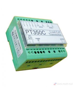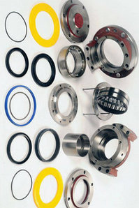

WFM-P Position Transmitter Module
Models:
WFM-P、WF-01、WF-M、WF-130、WFM-01, WF-S
Suitable for DKJ/ZKJ (DKZ/ZKZ) series electric actuators.
Drive energy: electric actuator
Attribute: attribute value
Features:
- Input voltage range: AC210V~AC255V
- Output 4~20mA signal through photoelectric isolation (can withstand 2000V surge voltage)
- Working temperature range: -25℃~+80℃
- Accuracy: 5‰
- Load resistance range: ≤750Ω
Common debugging method:
Step 1: The stroke limit mechanism has been adjusted before leaving the factory, especially the angular stroke electric actuator is not allowed to adjust the cam group. The cam debugging method: the cam mechanism is equipped with 4 cam pieces of different colors and numbers. Turn the actuator handwheel to make the valve to the closed position, adjust the screw slot No. 1 (2) (according to the site usage and model), push down to open and turn the cam plate in the closed direction until the cam just presses the closed (open) direction limit switch. Then turn the hand wheel in the reverse direction to make the valve fully open, use a screwdriver to align the No. 3 (4) adjustment screw slot, push down and turn the cam plate in the open direction until the cam just presses the open (close) limit switch (according to site usage and model). The adjustment of the midway switch is similar to the limit switch.
Step 2: Check whether the wiring is correct. Turn the handwheel to turn the actuator to the center position.
Step 3: Turn on the power and adjust the phase sequence.
Step 4: Measure the output of each contact.
Step 5: If it is ZPF-09, you need to adjust WF-01 to make the actuator output 4-20mA.
Debugging Method for WF-S Position Transmitter Module:
- Turn on the power and turn off the actuator. Look at the current output of terminals No. 1 and No. 2 (No. 1 is positive and No. 2 is negative). If the current direction is opposite, terminal 3 and terminal 5 are reversed. If the current value is too large or too small, you need to adjust the high-precision position sensor (potentiometer) in the stroke limiter to make its current value 0 mA or 4 mA.
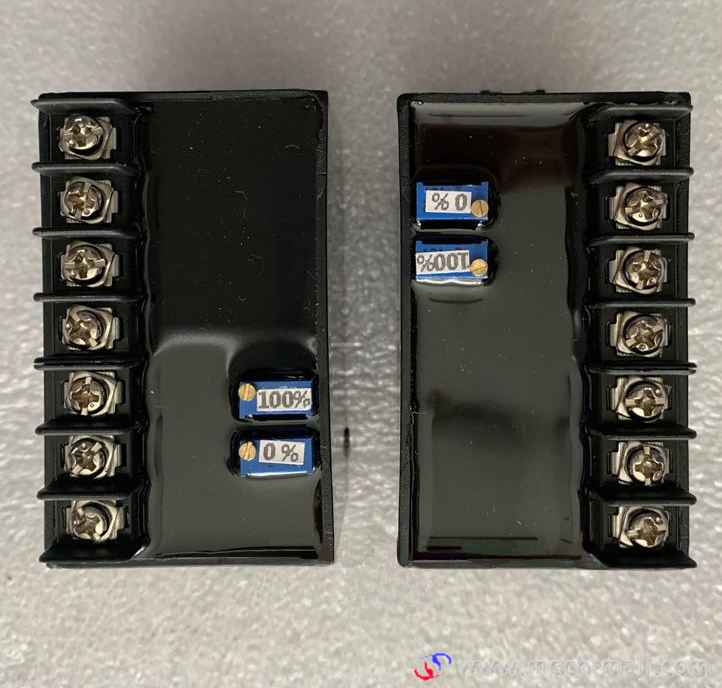
- Turn the actuator fully on and look at the current output of No. 1 and No. 2. If the current is too large or too small, you need to adjust the P2 (100%) full potentiometer to adjust to 10mA or 20mA.
- Close the actuator fully again and look at the current output of No. 1 and No. 2. There is a slight deviation in current at this time. Need to adjust P1 (0%) to full potentiometer to adjust to 0mA or 4mA.
- Repeating the adjustments twice can output accurate 4-20mA analog signals.